
Why?
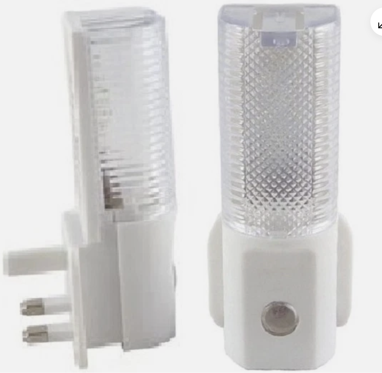
Remember cheap £1 LED night lights you could buy in Poundland few years ago? I do! You can still purchase them off Amazon and Ebay, example links below. I contacted the manufacturer and they confirmed these are still being produced!
https://www.amazon.co.uk/Electronics®-Energy-Automatic-Night-Sensor/dp/B07WHRMML9
https://www.ebay.co.uk/itm/204042402532
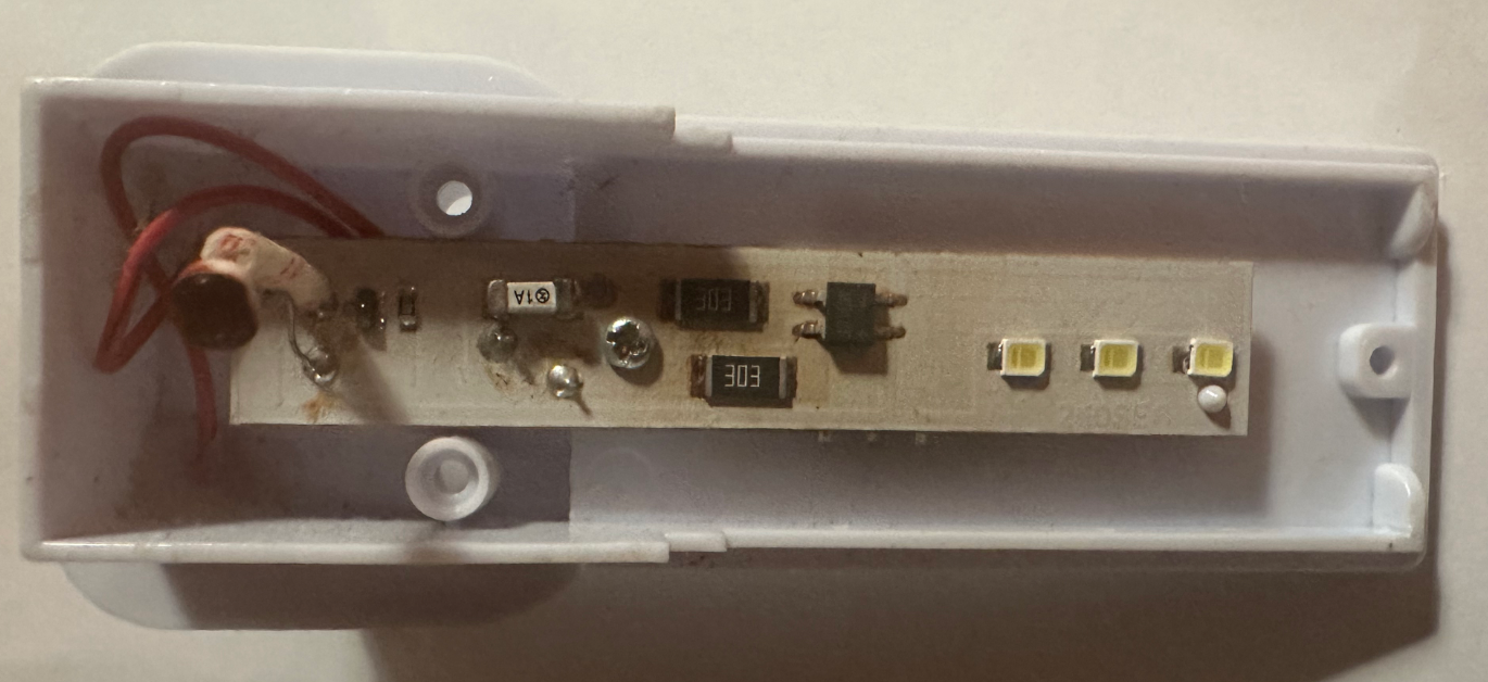
I disassembled one of these and found that they win not only consume power 24/7, not like you would expect them to, resulting in a huge waste of energy, and, well, your money, but are also overheating inside leading to PCB discoloration, which, to me, seems a bit unsafe.
So I decided to make them smart IoT by adding a micro-controller. This will not only allow them to turn on/off based on the solar elevation angle in your area (or any other control method you can think of, say, PIR), but I also added PIR and Siren to the project. One of the use cases is it will let you detect and alarm if there is a motion where you not expect it to be (say, ground floor in the night). The other – you might want to get alerted if there is any other “smart” event happened, like someone opened shed door or external gate. Your fantasy is the driver, the hardware and code example is there for you.
After measuring power consumption, I discovered that it is now using twice less power despite having an always-on “brains” in it, so it will save you about £1 per year in electricity! Once plugged in it will signal the correct initialisation by blinking the light few times and emitting few beeps. It then connects to solar elevation API and turns the light off (it is a daytime). Lastly, once it detects movement – it emits siren for the next minute or so to make you aware. Check the below video! First part – initiation sequence where it flashes light and emits short beeps to check everything is connected and operational. Towards the end of the video (if you are patient enough) it detects the motion and sounds a siren.
Board Design
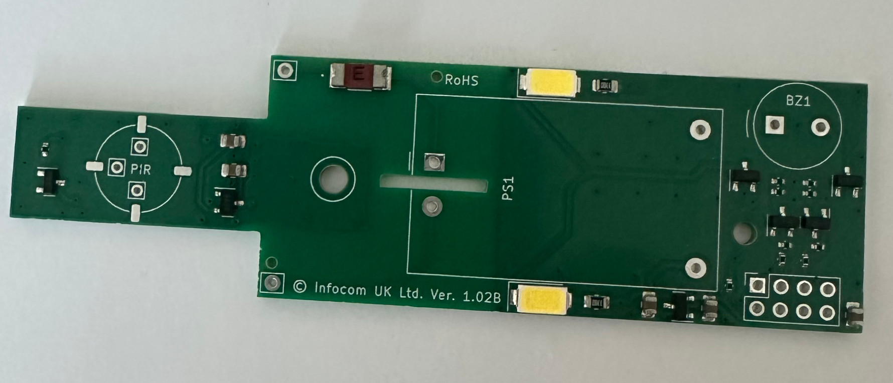
Initially, I thought of using DIY-friendly through hole components, however I quickly realised how tight is the space there! In addition to some constraints like AC spacing, power supply takes up a huge chunk, we also need space for buzzer, ESP-01S controller and PIR. In addition, some surface-mount components (like mini LED) are hard to solder (it is possible as some of them have solder pads protruding to sides) or, again, will consume too much space on the board and inside the enclosure, so I decided to go hybrid:
- make a PCB with all the SMD components on it
- leave PSU, 8-pin socket header, PIR (optional) and Buzzer (optional) for DIY-er to solder
The board now has the following components soldered on it:
- 2x LED
- 1x AC Fuse
- 2x LDO Voltage regulators (to isolate PIR from the noise generated by ESP-01S)
- 5x Transistors
- 12x Resistors
- 5x Capacitors
This method also allows you to choose functionality and skip the components you will not be using. Say, you just want smart IoT light – you can skip buzzer and PIR. When using PIR, you will need an infra-red lens to fit into the hole in the case, the one from AM312 PIR (or you can get some off AliExpress/Temu) fits perfectly with a little push from inside. And this is the end result:
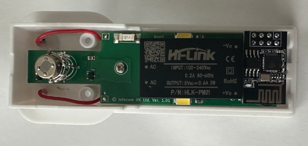
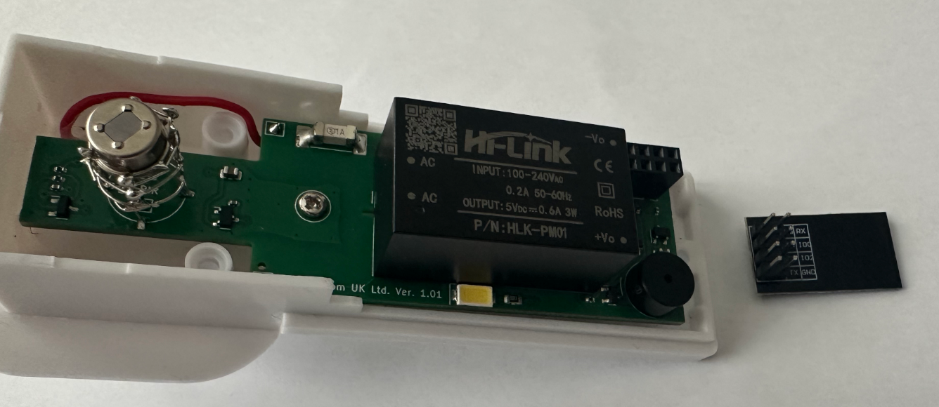

I will be using ESP-01S as main controller. Why? Because it is powerful enough, it fits well into the case, and it is easier to remove, re-program and fit it back into your device without need to re-solder or juggle the wires.
You might have noticed I created a little Faraday cage around PIR pins (to screen it from Wi-Fi noise), however I later discovered that even if I didn’t – there were no false alarm detections and this was probably not needed. It won’t hurt, still, and PCB comes with 4x pads for you solder one on. You can even use bronze or copper foil if you like, I added 4x pads for you to solder them on.
Parts Selection
The board itself – you can purchase off our eBay shop, thank you for supporting our project!
https://www.ebay.co.uk/itm/389593694894
Back to parts – I am using “Active” buzzer – the one you just need to supply power to. This is only because I found one in my drawer. You can also use “Passive” buzzer and use Arduino Tone library to play melody or have different tones of alarm if you like to, hardware is designed to accept any buzzer with 10mm diameter or less and 5mm (or 5.08mm) pin spacing. I had CMI-0955-05TH purchased from Mouser so I used that.
Rest of the parts – you can get them off AliExpress, or Amazon if you are impatient. Few links below.
Power Supply (PSU) – I designed the board to use very popular 5V power supply from Hi-Link – PM01. It provides 0.6A (3W) max power which is more than enough for this project. You can get them here:
https://s.click.aliexpress.com/e/_c3P6TRbZ
PIR – I ordered some AS312 PIR off AliExpress, they seem to work like a charm and never let me down so far:
https://s.click.aliexpress.com/e/_c2wPWHY3
PIR Lens – I used these ones as they fit perfectly into the hole on the case. Although the PIR itself is slightly out of focus as it lacks 2-3mm of PIR pin height, it works perfectly and didn’t bother me too much.I tried both fitting them onto PIR itself as well as fitting into the case – both methods show similar sensitivity:
https://s.click.aliexpress.com/e/_c3SnRgGJ
8-PIN header – there is plenty to choose from on AliExpress / Temu. I used these ones, few quid for a set of 50x – plenty to spare for the future projects!
https://s.click.aliexpress.com/e/_c3SYj3c7
I also purchased my ESP-01S (I didn’t test this with ESP-01 as I don’t like always-on red LED – it just drives me crazy) here:
https://s.click.aliexpress.com/e/_c4BRsKI7
From my experience, I prefer midpoint of the civil twilight (3° below the horizon, setting of -3). What I suggest you do is try turning your lights on at different sun angles and see which one you prefer. If you want to turn you light earlier – use angle above the horizon, e.g. setting of 3.
Smart Lighting Control by solar altitude
In my example project I used free Infocom’s Community API to receive solar altitude based on the location. You will just need to obtain a free token if you would like to follow this path. You are also welcome to use any other control method – hardware is there for you to play with! More on how to control lighting using solar altitude can be found here: External Lighting Control. API Token can be obtained here:
https://community.infocom.uk/client
Arduino IDE Code
Although many of you will probably say (and rightly so) that there was a better way or syntax to achieve the same result, I tend to focus on a clear code making it simpler and easier for the beginners. The below example will turn light on/off based on the solar angle, will detect motion and sound a siren for the next ~1 minute. This is purely to demonstrate how do you use the hardware. Oh, and it will emit short beeps twice an hour if it won’t be able to connect to API server (e.g. your Wi-Fi will be down). You then tune/change the code as you wish.
In this code you will also find a good example on how to process JSON data on Arduino ESP8266 chip as well as how to pass variables up to the HTTP server via GET request.
Once plugged into the socket – device should flash the lights few times and also produce three short beeps. If it doesn’t – try turning it off and on again or check your soldering/code.
#include <Arduino.h>
#include <ArduinoJson.h>
#include <ESP8266WiFiMulti.h>
#include <ESP8266HTTPClient.h>
// Please customize this section for the project to work
const float lat=51.52181; // latitude of where the device is, can be approximate
const float lon=-0.12718; // longitude of where the device is, can be approximate
const String token="your token here"; // generate a free token on https://community.infocom.uk/
// Enter SSID and PASS for up to 4x Wi-Fi networks below. Blank SSID means skip.
const char* ssid1 = "YOUR-WIFI-SSID1";
const char* pass1 = "YOUR-WIFI-SSID1-PASSWORD";
const char* ssid2 = "YOUR-WIFI-SSID2";
const char* pass2 = "YOUR-WIFI-SSID2-PASSWORD";
const char* ssid3 = "";
const char* pass3 = "";
const char* ssid4 = "";
const char* pass4 = "";
// No immediate changes are needed below this line for the project to work, but you are welcome to tune them if you want to.
const float lightThreshold = 3; // Solar elevation above horizon at which turn on/off the light
const float motionThreshold = 2; // Number of triggers required in each 60s to trigger alarm
const uint32_t connectTimeoutMs = 5000;
const int PinLED = 0;
const int PinBUZ = 2;
const int PinPIR = 3;
StaticJsonDocument<200> apiResponse;
DeserializationError error;
int StateLED = 0;
int StateBUZ = 0;
int StateMOTION = 0;
int i = 0;
float solarElevation;
ESP8266WiFiMulti wifiMulti;
WiFiClient client;
HTTPClient http;
String apiServer = "http://api.infocom.uk/solar/altitude/";
String serverPath = "";
String payload = "";
int httpResponseCode;
int counter = 0;
String serverName = "";
void beepOnce()
{
digitalWrite(PinBUZ, LOW);
delay (10);
digitalWrite(PinBUZ, HIGH);
delay (300);
}
void beepShort()
{
i = 0;
while (i < 3)
{
beepOnce();
i = i + 1;
}
}
void onLED()
{
if (StateLED == 0)
{
digitalWrite(PinLED, LOW);
StateLED = 1;
}
}
void offLED()
{
if (StateLED == 1)
{
digitalWrite(PinLED, HIGH);
StateLED = 0;
}
}
void onBUZ()
{
if (StateBUZ == 0)
{
digitalWrite(PinBUZ, LOW);
StateBUZ = 1;
}
}
void offBUZ()
{
if (StateBUZ == 1)
{
digitalWrite(PinBUZ, HIGH);
StateBUZ = 0;
}
}
void ICACHE_RAM_ATTR motionDetected()
{
StateMOTION = StateMOTION + 1;
if (StateMOTION > 1000)
{
StateMOTION = 1000;
}
}
void setup()
{
// if you want to report some debug data or actual state - un-comment the line below and change
// serverName = "http://192.168.1.98/solar/";
pinMode(PinBUZ, OUTPUT);
pinMode(PinLED, OUTPUT);
pinMode(PinPIR, INPUT);
digitalWrite(PinLED, HIGH);
digitalWrite(PinBUZ, HIGH);
delay(1000);
while (i < 5)
{
offLED();
delay(300);
onLED();
delay(20);
i = i + 1;
}
beepShort();
delay (5000); // Allow PIR to settle before installing interrupt processor
attachInterrupt(digitalPinToInterrupt(PinPIR), motionDetected, FALLING);
WiFi.persistent(true);
if (strlen(ssid1) !=0) { wifiMulti.addAP(ssid1, pass1); }
if (strlen(ssid2) !=0) { wifiMulti.addAP(ssid2, pass2); }
if (strlen(ssid3) !=0) { wifiMulti.addAP(ssid3, pass3); }
if (strlen(ssid4) !=0) { wifiMulti.addAP(ssid4, pass4); }
}
void loop()
{
if (wifiMulti.run(connectTimeoutMs) == WL_CONNECTED)
{
serverPath = apiServer + "?token=" + token + "&lon=" + lon + "&lat=" + lat;
http.begin(client, serverPath.c_str());
httpResponseCode = http.GET();
if (httpResponseCode == 200)
{
counter = 0;
payload = http.getString();
error = deserializeJson(apiResponse, payload);
solarElevation = apiResponse["value"];
http.end();
if ((solarElevation > -91) && (solarElevation < 91) && (solarElevation > lightThreshold))
{
offLED();
}
else
{
onLED();
}
if (serverName != "")
{
serverPath = serverName + "?value=" + solarElevation + "&RC=" + httpResponseCode + "&error=" + error.c_str() + "&LED=" + StateLED + "&BUZ=" + StateBUZ + "&MOTION=" + StateMOTION + "&ssid=" + WiFi.SSID() + "&rssi=" + WiFi.RSSI() + "×tamp=" + millis();
http.begin(client, serverPath.c_str());
httpResponseCode = http.GET();
http.end();
}
}
else
{
http.end();
}
counter = counter + 1;
i = 0;
while ((StateMOTION < motionThreshold) && (i < 60))
{
delay(1000);
i = i + 1;
}
if (StateMOTION >= motionThreshold)
{
onBUZ();
StateMOTION = 0;
}
else
{
offBUZ();
}
while (i < 60)
{
delay(1000);
i = i + 1;
}
if (counter > 30)
{
beepShort();
onLED();
counter = 0;
}
}
}Debugging
I don’t like Serial.begin() malarkey. When the ESP board is plugged into the project – there is no way to connect to serial. And when the ESP board is on the programmer – no actual inputs/outputs are connected. So, instead, I decided to use another HTTP server to post the debug data to. You just need to scroll down the code, uncomment the line and replace with your server name (or IP). I am running local apache server on my home server, 192.168.1.98, debug output example below. You probably have access to a random VPS or shared hosting I bet, if not – Oracle Cloud used to offer 2x free for life VPS – not sure if they still do that, but worth having a look!
root@x260:~# tail /var/log/apache2/access.log -n 100 -f | grep 10.128.5.188
10.128.5.188 - - [08/Feb/2026:13:19:53 +0000] "GET /solar/?value=22.14&RC=200&error=Ok&LED=0&BUZ=0&MOTION=0&ssid=GUEST111&rssi=-67×tamp=10190 HTTP/1.1" 200 393 "-" "ESP8266HTTPClient"
10.128.5.188 - - [08/Feb/2026:13:20:53 +0000] "GET /solar/?value=22.09&RC=200&error=Ok&LED=0&BUZ=0&MOTION=0&ssid=GUEST111&rssi=-67×tamp=70271 HTTP/1.1" 200 393 "-" "ESP8266HTTPClient"This now concludes the project, hope you found it interesting and have your ideas on what to do next. Spoiler – I have fully working home (and shed) alarm system built on this exact hardware! If you would like to support this website and purchase a board – you can do it on eBay, link below.
https://www.ebay.co.uk/itm/389593694894
Have fun! If you would like to discuss this project with others as well as view the schematic diagram, please join our facebook group at: